


| Selection Criteria and Calculations | |||
| For every application determine the TORQUE, MAXIMUM RPM, and for brakes, the BENDING MOMENT. | |||
| Then you can choose the correct shaft or coupling, and various accessories. | |||
|
Three Steps to Selection |
Example Selection Criteria |
||
| Metric | English | ||
| Line Tension (T) | 8 N | 1.8 lb | |
| Spool Weight (W) | 134 N | 30 lb | |
| Full Spool Radius (r) | 0.15 m | 5.9 in | |
| Spool Core Diameter (d) | 0.125 m | 0.41 ft | |
| Spool Centerline Distance (L) | 0.11m | 4.5 in | |
| Line Speed | 90m/min | 295 ft/min | |
| Step 1 - Torque | |
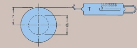 |
Example : |
| Full Spool Radius (r) x Line Tension (T) = Torque | |
| 0.15 m x 8 N = 1.2 Nm | |
| 5.9 in x 1.8 lb = 10.6 in lb | |
| Selection: In this example Model 523 or larger will work. | |
| Step 2 - Bending Moment | |
| The total weight multiplied by the Spool Centerline Distance (L). |
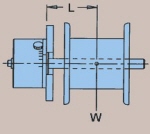 |
| Example : | |
| Spool Weight (W) x Spool Centerline Distance (L) = Bending Moment | |
| 134 N x 0.11 m = 14.7 Nm | |
| 30 lb x 4.5 in = 135 in lb | |
| Selection: In this example Model 610 or larger will work. | |
| Step 3 - Calculate MAX RPM | ||||||
| When a magnetic brake shaft is turning, mechanical energy is converted into thermal energy (watts). The amount of thermal energy (watts) is a function of the RPM and the TORQUE SETTING. | ||||||
| Example Calculation : | ||||||
| Max RPM = | Line Speed | = | 90 m/min | = | 295 ft/min | = 229 RPM |
| 3.14 x Core Dia.(d) | 3.14 x 0.125 m | 3.14 x 0.41 ft | ||||
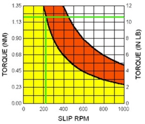 |
With the torque calculated in
Step 1 and the maximum RPM calculated in Step 3, refer to the
operating curves to determine if your application is within the
safe operating range of the brake. Selection: In this example, Model 523 or larger will work, however... CONSIDERING TORQUE, BENDING MOMENT, AND MAX RPM, THE BEST CHOICE IS MODEL 610. At the bottom of each product page you will find an operating curve for calculating the safe RPM vs. Torque
|